20 How To Use Fillet Command In Autocad Multiple Fillet Polyline

Autocad Fillet Tutorials To Create Fillet Command In Autocad Create 2d fillets. a round or fillet can be created between two objects of the same or different object types: 2d polylines, arcs, circles, ellipses, elliptical arcs, lines, rays, splines, and xlines. if the two selected objects are on the same layer, the arc defined is created on that layer. otherwise, the arc is created on the current layer. [message 2] . using whatever the current fillet radius setting is . [message 5] some possible causes [of its not working for @muhamed ragab92 in message 4] . picking sharp cornered polylines but not setting a non zero fillet radius first. but you don't need to actually fillet something to establish the.

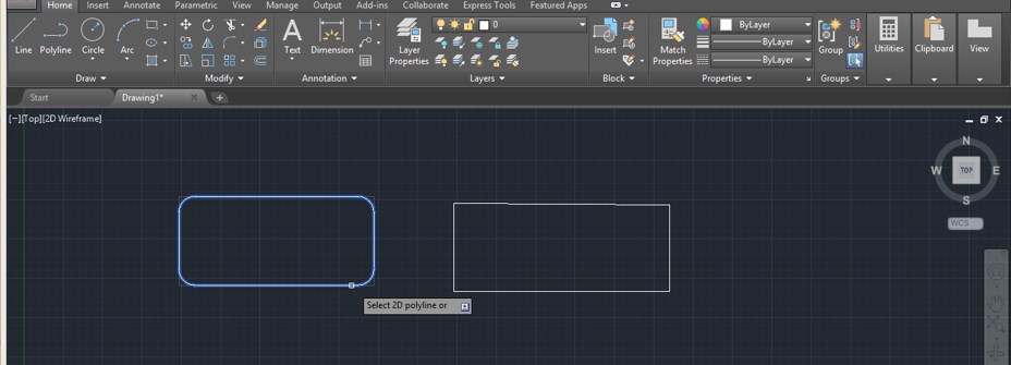
Complete Fillet Command In Autocad Youtube Hello friends! in this video, we will discuss about fillet command in autocad and its all sub commands: multiple fillet | polyline fillet | trim & no trimif. Add a fillet between two objects or line segments of a 2d polyline. click home tab modify panel chamfer and fillet drop down menu fillet. in the drawing area, select the first object or line segment that will define the points of tangency for the resulting arc. select the second object or line segment. tip: at the main prompt of the fillet. When the “fillet” command is used with “polylines”, there can be several outcomes. a sample closed “polyline” with dimensions is shown in figure 1. once a “fillet” radius has been set, in this case the radius has been set to a value of 20, two adjoining lines that comprise the “polyline” can be selected. The most important for fillet is “radius.”. use it to set the radius to use. pretty simple. it will keep that value until you change it. chamfer needs two distances. they can be the same (a 45* angle), or they can be different. that option is called “distance,” and it will prompt you for the first and second distance.

How To Use Fillet Command In Autocad Printable Online When the “fillet” command is used with “polylines”, there can be several outcomes. a sample closed “polyline” with dimensions is shown in figure 1. once a “fillet” radius has been set, in this case the radius has been set to a value of 20, two adjoining lines that comprise the “polyline” can be selected. The most important for fillet is “radius.”. use it to set the radius to use. pretty simple. it will keep that value until you change it. chamfer needs two distances. they can be the same (a 45* angle), or they can be different. that option is called “distance,” and it will prompt you for the first and second distance. To use fillet and chamfer on multiple sets of lines use the multiple option following the next steps: select the fillet command from the ribbon panel or type f and press enter. type m for multiple and press enter. select the first object. type r for radius, specify the fillet radius (for example, 1), and press enter. Autocad fillet command tutorial complete | radius, polyline, fillet corner, fillet parallel lines. this tutorial will teach you how to use fillet tool in aut.

Comments are closed.